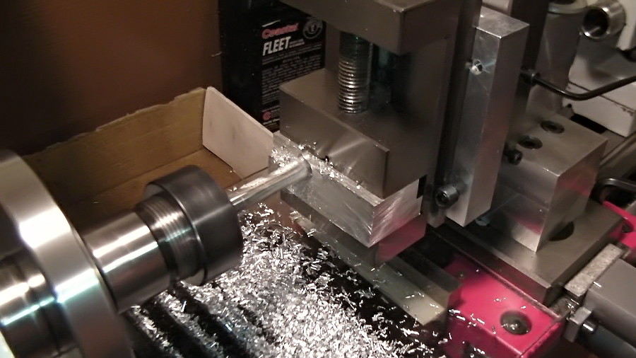
milling on the lathe and milling attachment:
Is it possible? What are the limitations?
Yes milling on the lathe is possible but with a lot of shortcomings and limitations. The most critical is the rigidity. Only by looking the Optimum D180, or any other similar mini lathe you can tell that the capabilities are limited. To reduce the vibrations that produced from the cutting forces we have to reduce the already limited size of the work piece, the distance that the work piece is extended from the vice and the depth of cut. The gibs must be properly adjusted and the axis that we don’t use must be locked.
The second limitation is the small travel of the axis and for that reason the position of the milling attachment must be planned carefully otherwise you are risking to reduce furthermore that travel.
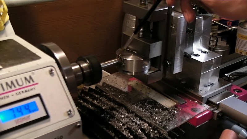 Another problem is the vertical position of the vice that in some cases makes difficult the positioning of the work piece.
Another issue is the time that it takes to set up and to align the milling attachment and the fact that we use the same machine for milling and lathe operations. Let’s assume that we are working on some lathe project and somewhere in the middle we need just a single milling future on our work piece. A five minutes job it can take more than an hour.
Those are some of the factors that making the milling on the lathe difficult but they are not the only ones. We will discuss in more depth some of those later on and we will also talk about the red thin lines that we should never cross.
If we try to make a parallelism between the milling machine and a motorcycle probable the “milling attachment” would be just a bicycle that we have attached a motor on it. So, if you plan to use the milling attachment only for some futures on some pieces it is fine. You can use that bicycle to travel for a few blocks. But if you plan to use it for a long distance trip you must be prepared for a big adventure.
What makes things worse.
If we ask from an experienced machinist to “ride” our bicycle he will laugh but finally by applying good milling techniques and by exploring the machine’s capabilities he will accomplish the task. At the other hand a newbie will look like a boy who trying to ride a bicycle for a first time. I believe that this is the biggest problem, the lack of experience.
Let’s jump into
Hold your horses mister!! There is something extremely important that I must mention before we continue. Do not, I repeat do not attempt any milling operation without eye protection. Chips are flying all over the place and they are very hot.
Keep your hands away from the cutters especially when the machine is turned off. We tend to feel safe when the machine it’s not running but be aware you can cut yourself badly.
Climb milling vs Conventional milling
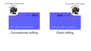 From Wikipedia
” Conventional milling (left): The chip thickness starts at zero thickness, and increases up to the maximum. The cut is so light at the beginning that the tool does not cut, but slides across the surface of the material, until sufficient pressure is built up and the tooth suddenly bites and begins to cut. This deforms the material (at point A on the diagram, left), work hardening it, and dulling the tool. The sliding and biting behaviour leaves a poor finish on the material.
Climb milling (right): Each tooth engages the material at a definite point, and the width of the cut starts at the maximum and decreases to zero. The chips are disposed behind the cutter, leading to easier swarf removal. The tooth does not rub on the material, and so tool life may be longer. However, climb milling can apply larger loads to the machine, and so is not recommended for older milling machines, or machines which are not in good condition. This type of milling is used predominantly on mills with a backlash eliminator. “
From the above looks like that Climb milling has some benefits in comparison to Conventional milling but if we focus on the two last underlined phrases looks that we have some serious disadvantages in our case. About the “larger loads” I believe that we don’t need more explanations, this is something that we definitely need to avoid but it seems that it something is wrong with the backlash also.
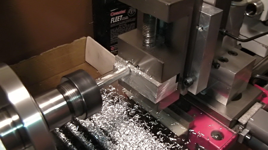 Ok, let’s take our first face milling cuts on some piece of aluminum. But that looks like climb milling or what? Actually it’s not. Ok, let’s take our first face milling cuts on some piece of aluminum. But that looks like climb milling or what? Actually it’s not.
|
||
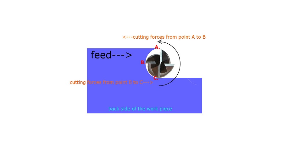 Let’s take a closer look. Notice that the highest point of the cutter matches with the highest point of the work piece. The cutter has been placed strategically that way. From the point “A” that the cutter begins to cut and until point “B” performs conventional milling when from point “B” to point “C” performs climb milling. A good question at this point is, are we facing any problems since at the half way our cutter performs climb milling? The answer is no. Why? Because each tooth of the cutter penetrates successfully into the work piece before point “B”. From so on the tooth itself prevents the work piece from moving, so the backlash doesn’t affect our work any more. This is the preferable way of face milling since we can remove a lot of material with less vibrations. Let’s take a closer look. Notice that the highest point of the cutter matches with the highest point of the work piece. The cutter has been placed strategically that way. From the point “A” that the cutter begins to cut and until point “B” performs conventional milling when from point “B” to point “C” performs climb milling. A good question at this point is, are we facing any problems since at the half way our cutter performs climb milling? The answer is no. Why? Because each tooth of the cutter penetrates successfully into the work piece before point “B”. From so on the tooth itself prevents the work piece from moving, so the backlash doesn’t affect our work any more. This is the preferable way of face milling since we can remove a lot of material with less vibrations. |
||
| https://www.youtube.com/embed/N3ahADbc_qs
|
||
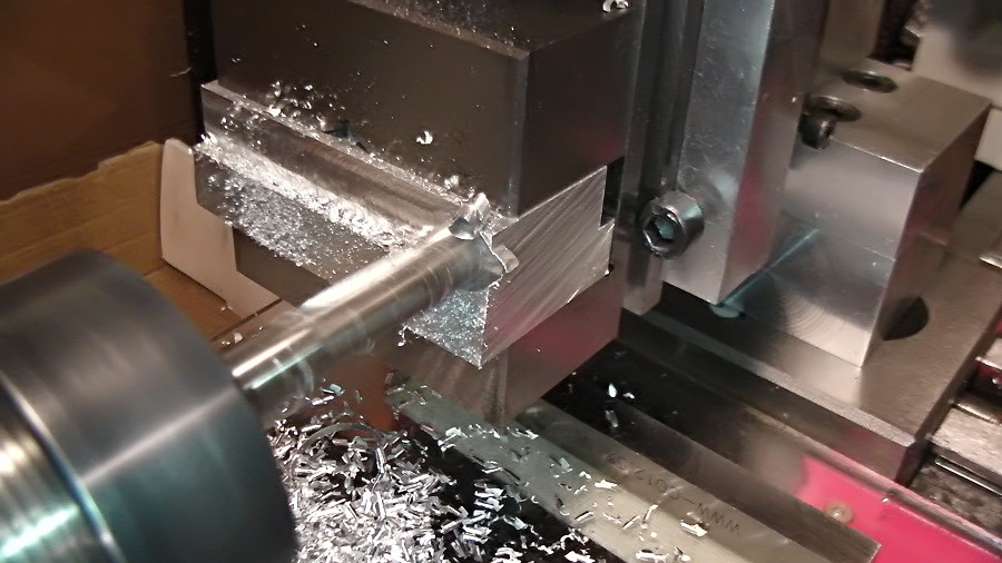 When you reach at the exit point reduce the feed at the one quarter. What feed? That’s a good question.My experience has shown to me that at 500 RPM the progress is slow and at 1000 RPM or more things is getting too dangerous. So, my suggestion is simple, start with 700 RPM and take a light cut in depth of 0.3mm. Increase the feed progressively until you get a nice sense to your hand, not too fast or too slow and comfortable to work with. Face off the entire surface without making any changes in the depth of cut.Now in the second pass you can increase the depth of cut to 0.6mm and test if you are getting any vibrations. Make several passes and keep increasing the depth of cut progressively until you start to feel some vibrations. At this point you should take one step back and decrease the depth of cut a little bit. Now you have determined the maximum allowable depth of cut at this speed with a nice and comfortable feed.Let’s talk about what other factors affect the depth of cut, speed and feed. When you reach at the exit point reduce the feed at the one quarter. What feed? That’s a good question.My experience has shown to me that at 500 RPM the progress is slow and at 1000 RPM or more things is getting too dangerous. So, my suggestion is simple, start with 700 RPM and take a light cut in depth of 0.3mm. Increase the feed progressively until you get a nice sense to your hand, not too fast or too slow and comfortable to work with. Face off the entire surface without making any changes in the depth of cut.Now in the second pass you can increase the depth of cut to 0.6mm and test if you are getting any vibrations. Make several passes and keep increasing the depth of cut progressively until you start to feel some vibrations. At this point you should take one step back and decrease the depth of cut a little bit. Now you have determined the maximum allowable depth of cut at this speed with a nice and comfortable feed.Let’s talk about what other factors affect the depth of cut, speed and feed.
Buy some small bars of Aluminum, Alloy 6061 is an excellent choice or 5251 and buy also a few HSS 2 Flute or 3 Flute End Mills especially for Aluminum or Non-Ferrous materials. Start practicing and test all of the above by yourself.
|
||
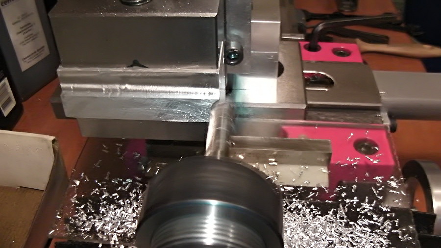 Raise the work for the next cut. Notice again that the highest point of the cutter matches with the highest point of the work piece. I mean from the portion that has been left. Like the exit point reduce the feed on the entrance also. Raise the work for the next cut. Notice again that the highest point of the cutter matches with the highest point of the work piece. I mean from the portion that has been left. Like the exit point reduce the feed on the entrance also.
|
||
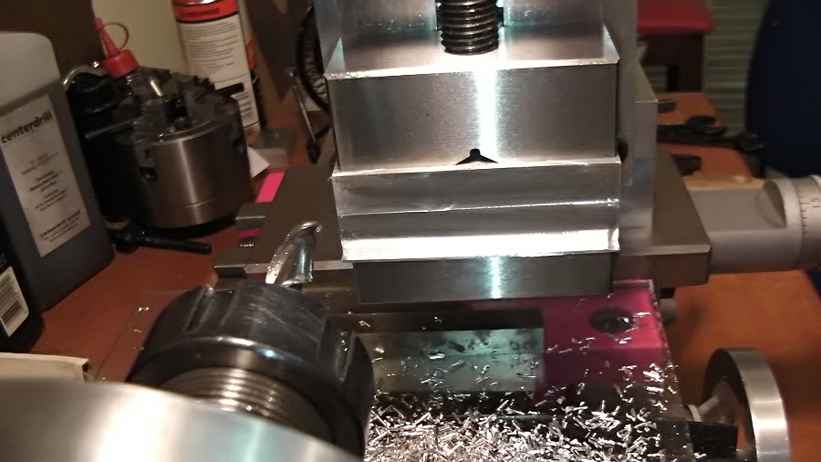 Ok, I just finished the second pass but there’s still something left, 1mm of material or so. I used a 10mm End Mill but maybe I should have chosen a 12mm End Mill instead. Usually we prefer the biggest end mill possible for face milling since we want to remove a lot of material fast. But it’s a good idea to take the height of the work into consideration. For example In this case the 10mm end mill is not enough to complete the operation into two phases and with a 16mm end mill at the second pass we will use only some portion of the end mill which is not ideal. Keep that in mind when you choose an end mill for face milling. As I mention earlier the diameter of the cutter will affect the cutting speed also but bear with me I will talk about this later. Ok, I just finished the second pass but there’s still something left, 1mm of material or so. I used a 10mm End Mill but maybe I should have chosen a 12mm End Mill instead. Usually we prefer the biggest end mill possible for face milling since we want to remove a lot of material fast. But it’s a good idea to take the height of the work into consideration. For example In this case the 10mm end mill is not enough to complete the operation into two phases and with a 16mm end mill at the second pass we will use only some portion of the end mill which is not ideal. Keep that in mind when you choose an end mill for face milling. As I mention earlier the diameter of the cutter will affect the cutting speed also but bear with me I will talk about this later. |
||
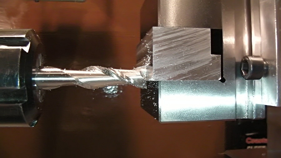 Although is not always possible to complete the face milling operation with even cuts and some material could be left over. We know that we can’t use climb milling but I will not recommend conventional milling ether. The milling attachment it will observe more easily the horizontal cutting forces than the vertical. Although is not always possible to complete the face milling operation with even cuts and some material could be left over. We know that we can’t use climb milling but I will not recommend conventional milling ether. The milling attachment it will observe more easily the horizontal cutting forces than the vertical.
|
||
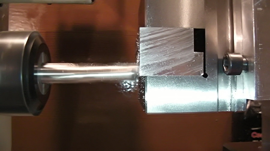 So I will place the end mill in the center of the remaining material and I will reduce the feed for the final cut. So I will place the end mill in the center of the remaining material and I will reduce the feed for the final cut.
|
||
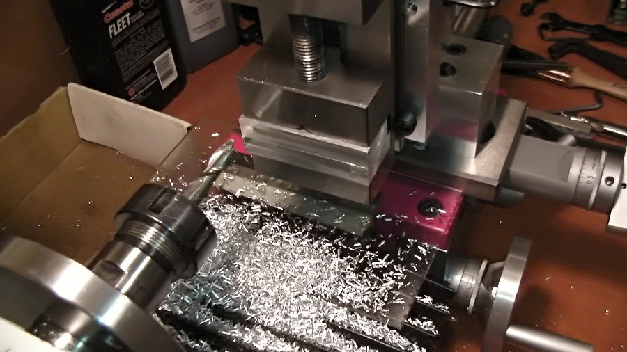 We are just complete our first face milling operation. We are just complete our first face milling operation.
|
||
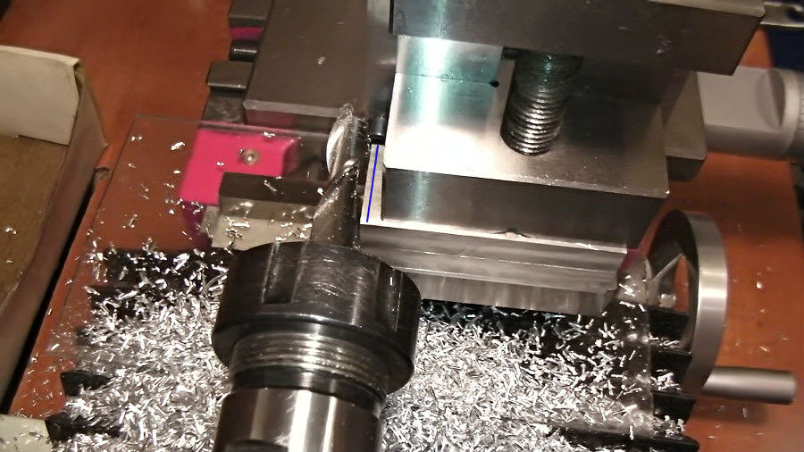 Next I will lower my work for side milling. I will use the same speed but I will reduce a lot the depth of cut. Next I will lower my work for side milling. I will use the same speed but I will reduce a lot the depth of cut.
|
||
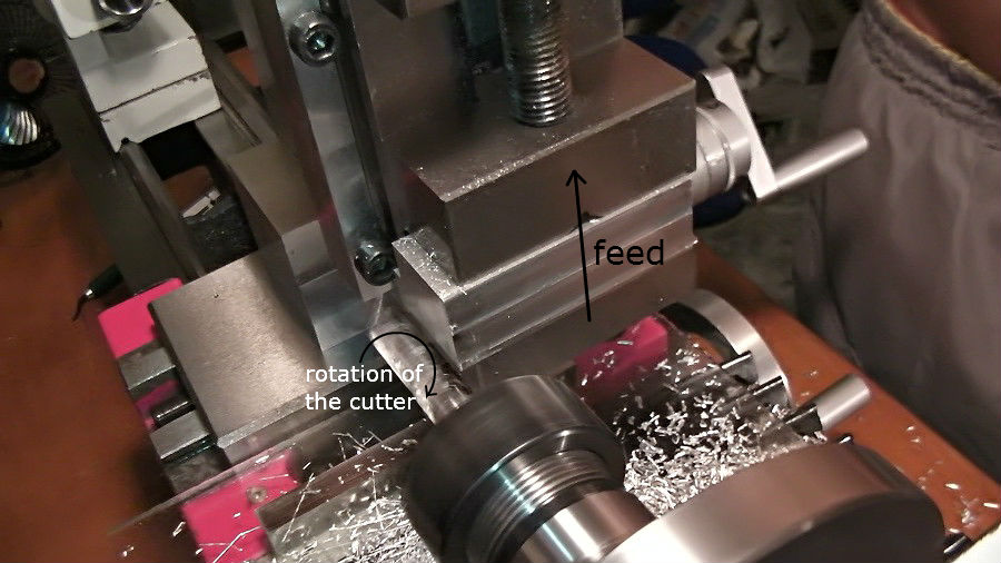 Notice again the rotation of the cutter and the feed direction. Yes, this is conventional milling.End of page 2 Notice again the rotation of the cutter and the feed direction. Yes, this is conventional milling.End of page 2
|
||
Tool Diameter and Speed
You are probably already familiar with how the speed changes by the work piece diameter on lathe operations. The bigger the diameter the less of the cutting speed. The same principles apply on milling operations too with the only difference that we use the tool’s diameter to determine the speed. For the previews operations we have used a 12mm HSS End mill on a piece of aluminum at 750RPM. What I’m using as a rule is to increase or decrease the speed by 7.5% approximately for every 2mm of change in the tool diameter. For example with a 16mm End mill my speed will be 640RPM, approximately 15% less than 750RPM. Let’s take a look at the chart below.
Diameter – Speed
16mm ~ 640RPM
12mm ~ 750RPM
10mm ~ 800RPM
8mm ~ 870RPM
6mm ~ 930RPM
This rule it may have been proved effective but in the reality the optimum cutting speed is increasing dramatically as the cutters diameter decreases. For example the recommended speed for a 3mm End Mill will be some thousands more than the maximum speed of the D180. So, for cutters smaller than 4mm I sagest you to use the highest speed possible, always use some cutting fluid and reduce the feed end the depth to minimum. Otherwise you will break the cutter when you barely touch the work.
Materials and Speed
A different material will affect our cutting speeds in any way? Yes, again as on lathe operations the same principles apply on milling too. For example for steel we will decrease the speed approximately by 15% but for brass we must increase it by 15-20%. For brass always use good quality tools and razor sharp.
Carbide vs HSS
Can we use carbide tool? Generally I prefer HSS End Mills since the carbide tools demand much higher speed and more aggressive cuts to perform well. The only exception is when I need to cut a very hard material, stainless steel for example, but I’m taking very light cuts with small cutters and only in very small pieces. I should mention also that for steel I’m using HSS tools with an additional 8% of cobalt on it and can be identified by the letters HSS-Co8. They are much harder than plane HSS tools.
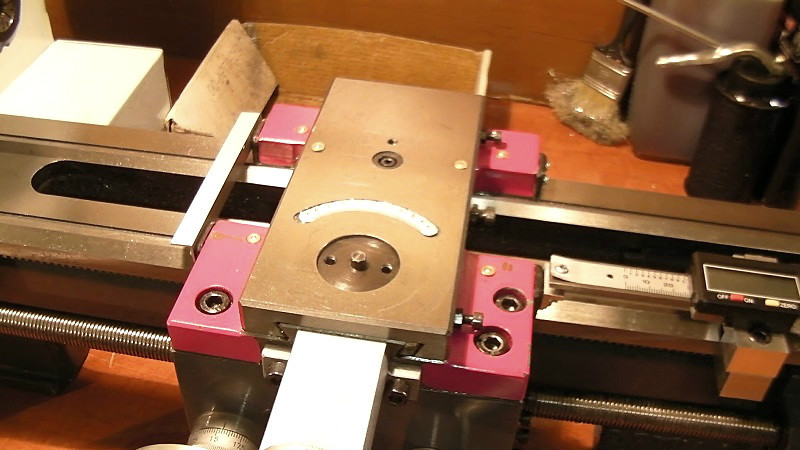
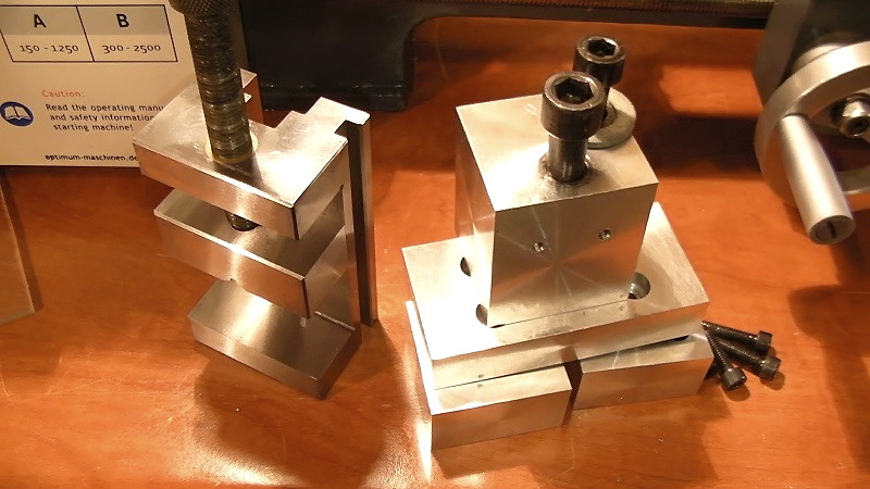
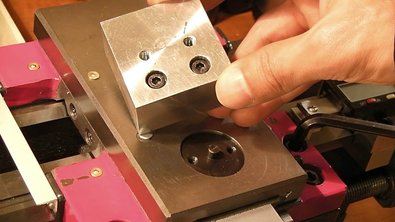
Those are a few tips to help you with your first milling operations on the lathe. Of course we have more to talk about, like how to square the work, how square is actually a square and how to find out, plunge milling, fly cutters and many more but first I want to talk for my milling attachment and to give you some more details because I’m getting a lot of questions about it.
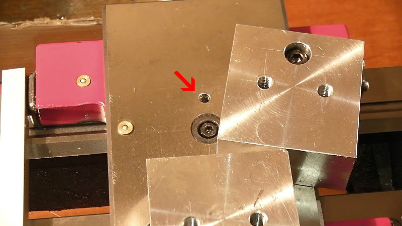
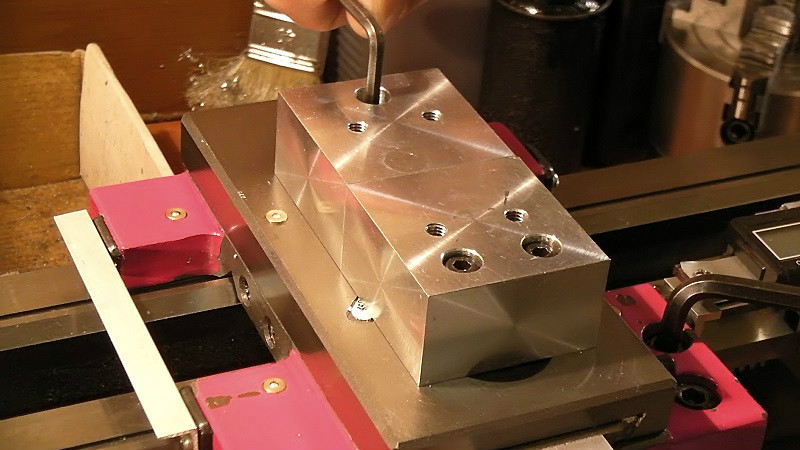
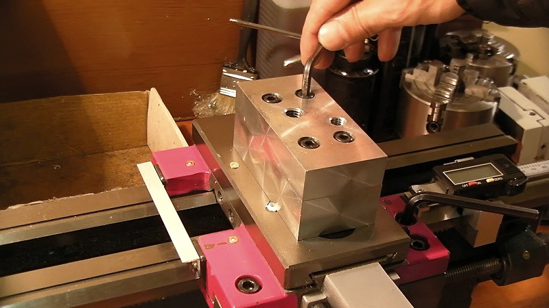
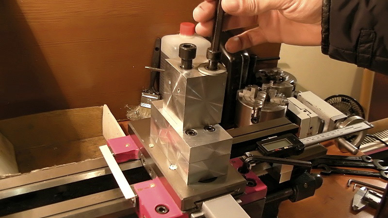
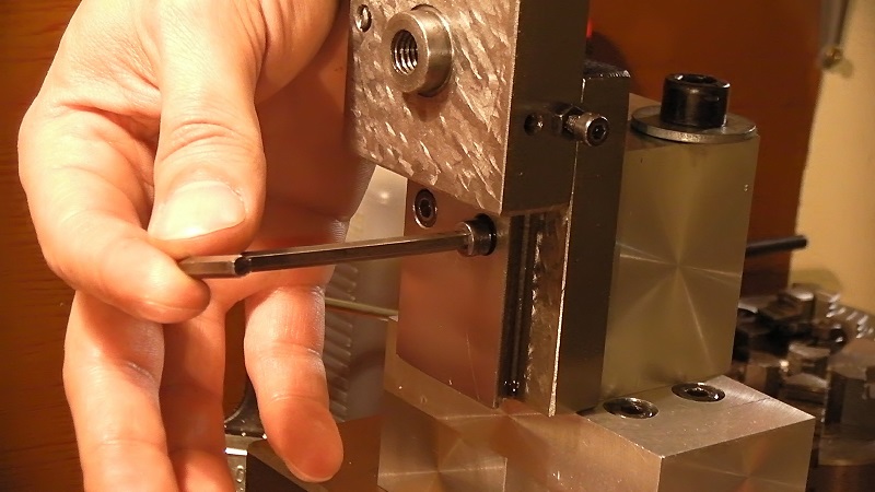
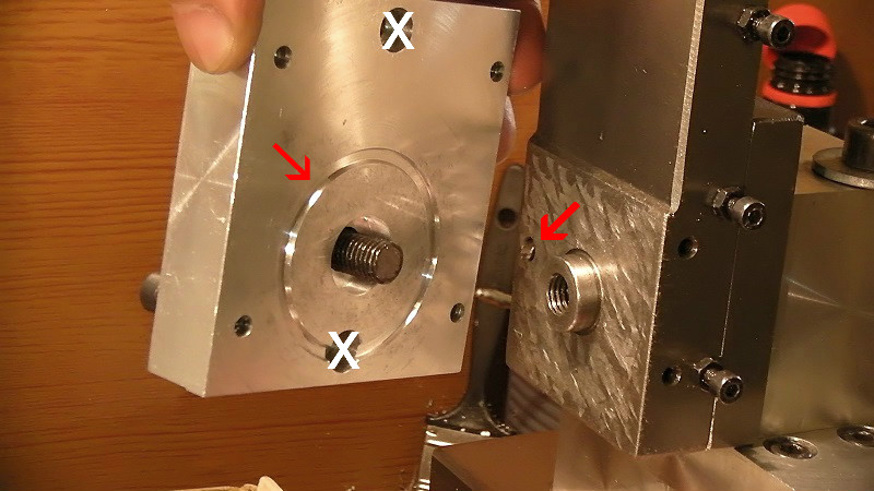
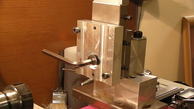
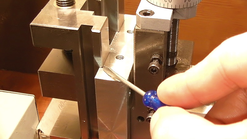
My milling attachment
 |
 |
 |
 |
 |
 |
 |
 |
 |
 |
 |
 |
 |
 |
 |
 |
 |

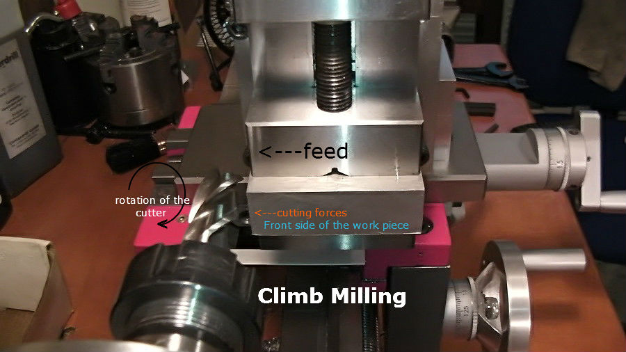 Let’s take a look at some live picture from Climb milling and notice the direction of feed and the direction of the cutting forces.
 let’s see in conventional milling. The cutter from the point that touches the work piece and on, rotates against the direction of feed when in climb milling the cutter rotates in the same direction with feed.
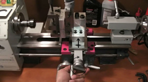
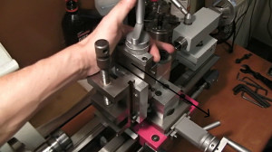 and replicate the cutting forces from conventional milling by hand, in other words push against the feed, the cross slide it will remain stationary.
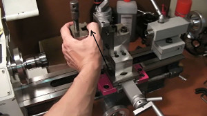
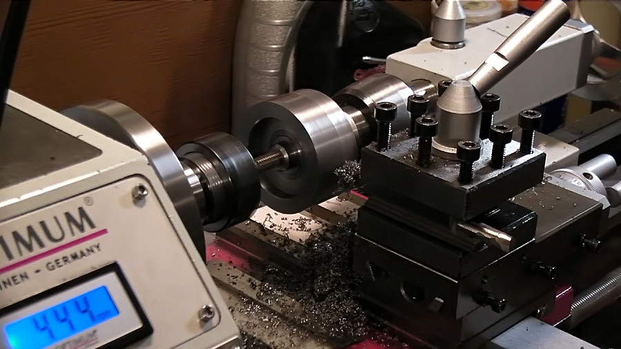 That means that the cutter at the most critical point, the point of impact, it will move the work piece in the same direction with it and it will cancel the basic principle of the metal-cutting which is, a knife-shaped tool, harder than the material that needs be to cut, moves to the opposite direction of the material. The end mill it will fail to take the cut, instead it will climb or ride onto the work piece and it will force it out of the vice until the work piece build enough pressure to stop the end mill.
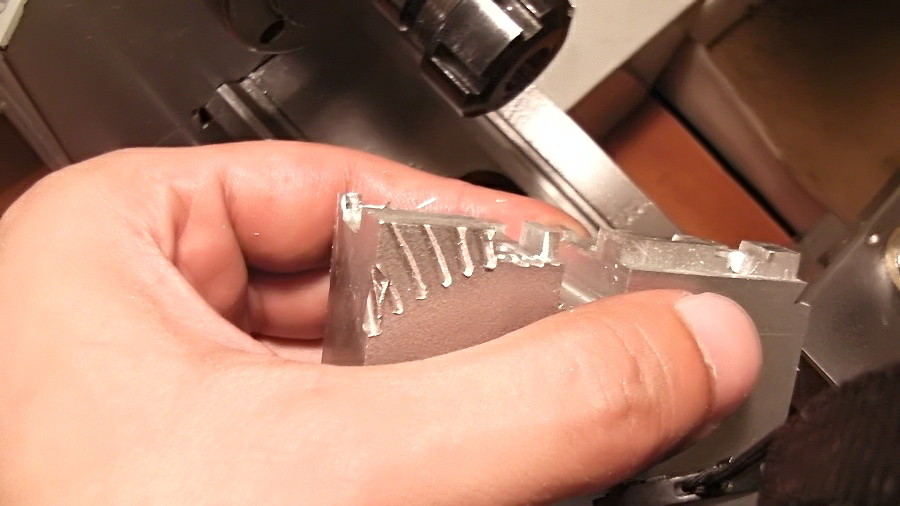 Those are the results of climb milling on a piece of aluminum. Whatever you do, do not attempt climb milling with the milling attachment.End of page 1